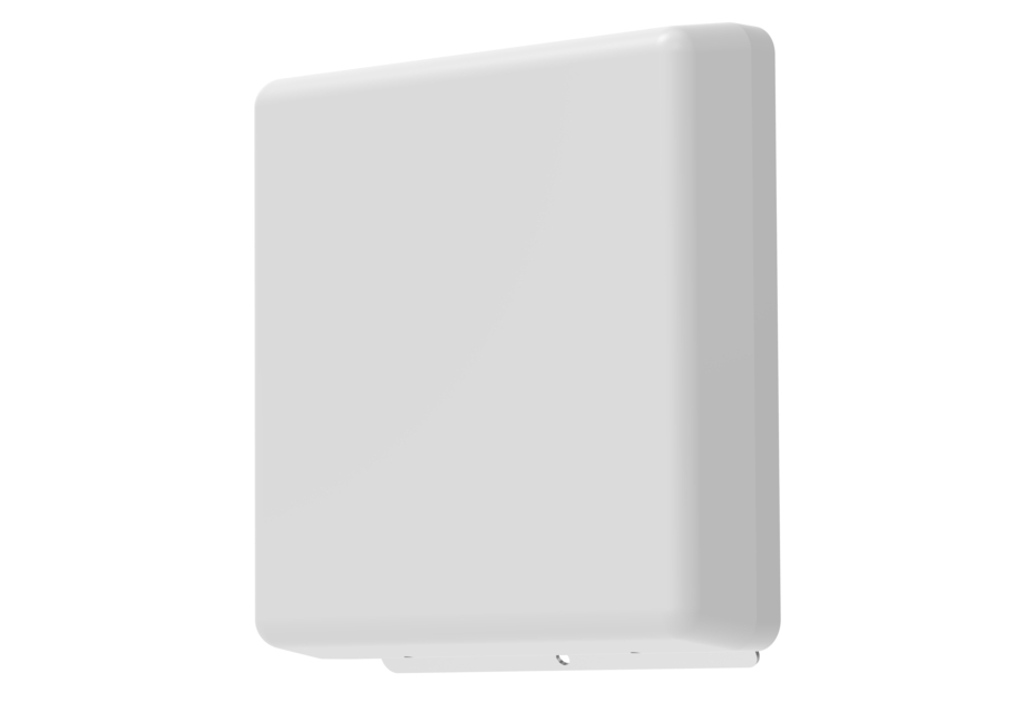
VV-65T-F-V3
4-port small cell antenna, 4x 1695–2690 MHz, 65° HPBW, fixed electrical tilt
Features and Benefits
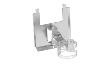
- Designed for strand mounting with OEM equipment
Specifications
General Specifications
| Antenna Type | Small Cell |
| Band | Single band |
| Color | Light Gray (RAL 7035) |
| Grounding Type | RF connector inner conductor and body grounded to reflector and mounting bracket |
| Performance Note | Outdoor usage |
| Radome Material | ASA+PC, UV stabilized |
| Radiator Material | Low loss circuit board |
| Reflector Material | Aluminum |
| RF Connector Interface | NEX10 Female |
| RF Connector Location | Rear |
| RF Connector Quantity, mid band | 4 |
| RF Connector Quantity, total | 4 |
Dimensions
| Width | 200 mm | 7.874 in |
| Depth | 44 mm | 1.732 in |
| Length | 200 mm | 7.874 in |
| Net Weight, antenna only | 0.72 kg | 1.587 lb |
Array Layout
| Click on image to enlarge. |

Port Configuration
| Click on image to enlarge. |

Electrical Specifications
| Impedance | 50 ohm |
| Operating Frequency Band | 1695 – 2690 MHz |
| Polarization | ±45° |
| Total Input Power, maximum | 200 W |
Electrical Specifications
| Y1,Y2 | Y1,Y2 | Y1,Y2 | Y1,Y2 | |
| Frequency Band, MHz | 1695–1920 | 1920–2180 | 2300–2500 | 2500–2690 |
| RF Port | 1-4 | 1-4 | 1-4 | 1-4 |
| Gain, dBi | 10.3 | 10.8 | 11.4 | 11.9 |
| Beamwidth, Horizontal, degrees | 75 | 69 | 69 | 64 |
| Beamwidth, Vertical, degrees | 42.5 | 37.8 | 32.2 | 30.8 |
| Beam Tilt, degrees | 4 | 4 | 4 | 4 |
| USLS (First Lobe), dB | 19 | 14 | 13 | 12 |
| Front-to-Back Ratio, Copolarization 180° ± 30°, dB | 28 | 29 | 26 | 27 |
| Front-to-Back Total Power at 180° ± 30°, dB | 19 | 19 | 21 | 22 |
| Isolation, Cross Polarization, dB | 22 | 22 | 22 | 22 |
| Isolation, Inter-band, dB | 22 | 22 | 22 | 22 |
| VSWR | Return loss, dB | 1.5 | 14.0 | 1.5 | 14.0 | 1.5 | 14.0 | 1.5 | 14.0 |
| PIM, 3rd Order, 2 x 20 W, dBc | -153 | -153 | -153 | -153 |
| Input Power per Port, maximum, watts | 50 | 50 | 50 | 50 |
Electrical Specifications, BASTA
| Frequency Band, MHz | 1695–1920 | 1920–2180 | 2300–2500 | 2500–2690 |
| Gain by all Beam Tilts, average, dBi | 10.1 | 10.7 | 11.1 | 11.7 |
| Gain by all Beam Tilts Tolerance, dB | ±0.4 | ±0.3 | ±0.5 | ±0.3 |
| Beamwidth, Horizontal Tolerance, degrees | ±3 | ±5 | ±2 | ±2 |
| Beamwidth, Vertical Tolerance, degrees | ±2.7 | ±3 | ±1.4 | ±0.6 |
| CPR at Boresight, dB | 19 | 21 | 20 | 25 |
| CPR at Sector, dB | 11 | 8 | 6 | 7 |
Mechanical Specifications
| Wind Loading @ Velocity, frontal | 60.8 N @ 150 km/h (13.7 lbf @ 150 km/h) |
| Wind Loading @ Velocity, lateral | 13.4 N @ 150 km/h (3.0 lbf @ 150 km/h) |
| Wind Loading @ Velocity, rear | 60.8 N @ 150 km/h (13.7 lbf @ 150 km/h) |
| Wind Speed, maximum | 200 km/h (124 mph) |
Packaging and Weights
| Width, packed | 230 mm | 9.055 in |
| Depth, packed | 93 mm | 3.661 in |
| Length, packed | 230 mm | 9.055 in |
| Weight, gross | 0.75 kg | 1.653 lb |
Regulatory Compliance/Certifications
| Agency | Classification |
| ISO 9001:2015 | Designed, manufactured and/or distributed under this quality management system |
| ROHS | Compliant |
|
CHINA-ROHS
|
Below maximum concentration value |
| REACH-SVHC | Compliant as per SVHC revision on www.commscope.com/ProductCompliance |
| UK-ROHS | Compliant |
General Specifications
| Antenna Type | Small Cell |
| Band | Single band |
| Color | Light Gray (RAL 7035) |
| Grounding Type | RF connector inner conductor and body grounded to reflector and mounting bracket |
| Performance Note | Outdoor usage |
| Radome Material | ASA+PC, UV stabilized |
| Radiator Material | Low loss circuit board |
| Reflector Material | Aluminum |
| RF Connector Interface | NEX10 Female |
| RF Connector Location | Rear |
| RF Connector Quantity, mid band | 4 |
| RF Connector Quantity, total | 4 |
Dimensions
| Width | 200 mm | 7.874 in |
| Depth | 44 mm | 1.732 in |
| Length | 200 mm | 7.874 in |
| Net Weight, antenna only | 0.72 kg | 1.587 lb |
Electrical Specifications
| Impedance | 50 ohm |
| Operating Frequency Band | 1695 – 2690 MHz |
| Polarization | ±45° |
| Total Input Power, maximum | 200 W |
Electrical Specifications
| Y1,Y2 | Y1,Y2 | Y1,Y2 | Y1,Y2 | |
| Frequency Band, MHz | 1695–1920 | 1920–2180 | 2300–2500 | 2500–2690 |
| RF Port | 1-4 | 1-4 | 1-4 | 1-4 |
| Gain, dBi | 10.3 | 10.8 | 11.4 | 11.9 |
| Beamwidth, Horizontal, degrees | 75 | 69 | 69 | 64 |
| Beamwidth, Vertical, degrees | 42.5 | 37.8 | 32.2 | 30.8 |
| Beam Tilt, degrees | 4 | 4 | 4 | 4 |
| USLS (First Lobe), dB | 19 | 14 | 13 | 12 |
| Front-to-Back Ratio, Copolarization 180° ± 30°, dB | 28 | 29 | 26 | 27 |
| Front-to-Back Total Power at 180° ± 30°, dB | 19 | 19 | 21 | 22 |
| Isolation, Cross Polarization, dB | 22 | 22 | 22 | 22 |
| Isolation, Inter-band, dB | 22 | 22 | 22 | 22 |
| VSWR | Return loss, dB | 1.5 | 14.0 | 1.5 | 14.0 | 1.5 | 14.0 | 1.5 | 14.0 |
| PIM, 3rd Order, 2 x 20 W, dBc | -153 | -153 | -153 | -153 |
| Input Power per Port, maximum, watts | 50 | 50 | 50 | 50 |
Electrical Specifications, BASTA
| Frequency Band, MHz | 1695–1920 | 1920–2180 | 2300–2500 | 2500–2690 |
| Gain by all Beam Tilts, average, dBi | 10.1 | 10.7 | 11.1 | 11.7 |
| Gain by all Beam Tilts Tolerance, dB | ±0.4 | ±0.3 | ±0.5 | ±0.3 |
| Beamwidth, Horizontal Tolerance, degrees | ±3 | ±5 | ±2 | ±2 |
| Beamwidth, Vertical Tolerance, degrees | ±2.7 | ±3 | ±1.4 | ±0.6 |
| CPR at Boresight, dB | 19 | 21 | 20 | 25 |
| CPR at Sector, dB | 11 | 8 | 6 | 7 |
Mechanical Specifications
| Wind Loading @ Velocity, frontal | 60.8 N @ 150 km/h (13.7 lbf @ 150 km/h) |
| Wind Loading @ Velocity, lateral | 13.4 N @ 150 km/h (3.0 lbf @ 150 km/h) |
| Wind Loading @ Velocity, rear | 60.8 N @ 150 km/h (13.7 lbf @ 150 km/h) |
| Wind Speed, maximum | 200 km/h (124 mph) |
Packaging and Weights
| Width, packed | 230 mm | 9.055 in |
| Depth, packed | 93 mm | 3.661 in |
| Length, packed | 230 mm | 9.055 in |
| Weight, gross | 0.75 kg | 1.653 lb |
| Click on image to enlarge. |
| Click on image to enlarge. |
Regulatory Compliance/Certifications
| Agency | Classification |
| ISO 9001:2015 | Designed, manufactured and/or distributed under this quality management system |
| ROHS | Compliant |
|
CHINA-ROHS
|
Below maximum concentration value |
| REACH-SVHC | Compliant as per SVHC revision on www.commscope.com/ProductCompliance |
| UK-ROHS | Compliant |
Documentation & Downloads
Assembly Drawing
Product Information
Product Specification
Warranty
Assembly Drawing
Product Compliance Documentation
Product Information
Product Specification
Warranty
Related Products and Accessories
Other Ways to Browse
