 This blog post is adapted from content in the Microwave Radio Antenna Link Fundamentals online course, which is available through the CommScope Infrastructure Academy, and continues our look at the various performance characteristics of microwave antennas.
Radiation pattern envelopes (RPE) are becoming increasingly important in the planning and operation of microwave links and networks. Frequency congestion is becoming a massive problem in many areas where the number of links being deployed for LTE and metro cells is rapidly increasing and it is expected that the number of antennas with low side lobes being deployed will continue to rise.
But what is a radiation pattern envelope? Let’s start first with the radiation pattern, which demonstrates the antenna's gain as a function of angle and provides an instant view of the antenna's directive properties. Think of a radiation pattern as a picture of the antenna's sensitivity as a function of angle. The radiation patterns are measured both in the antenna’s co-polarised mode of operation, and also in the cross-polarised condition at specified spot frequency bands within the operational band of the antenna.
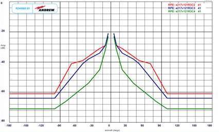
All the measured patterns are brought together into a single display, which is made available to the market in the form of a radiation pattern envelope (or RPE). The RPE is a straight line segmented graphical representation of the measured radiation patterns and includes margin to accommodate variations due to manufacturing tolerances. Although this envelope approach is quite conservative, it is has been proven to be much more reliable for link planning compared to using discrete (individual) radiation patterns.
An antenna’s RPE is normally compared against major regulatory requirements, which govern what antennas can be deployed in certain regions or countries. These organisations include the European Telecommunications Standards Institute (ETSI) and the Federal Communications Commission (FCC) in the USA. There may also be local regulatory specifications that antennas need to meet before they can be deployed.
Regulatory requirements are grouped into frequency ranges and classifications to ensure that the correct antenna is selected depending on the level of interference immunity required in the area of the link. ETSI Class 3 and FCC Category A patterns have been the “norm” for many years, but recently the need for antennas with ETSI Class 4 RPEs being deployed has increased thanks to the lack of available spectrum and the need for maximising capacity and reducing network downtime. These low side lobe antennas provide improved immunity against interference from both inside and outside your network and, in many cases, allow a link to be closed using smaller antennas.
You can view an RPE on page five of this white paper about ETSI Class 4 antennas, which includes an analysis of a real-world microwave network. CommScope’s ETSI Class 4 antennas are sold under the brand Sentinel.
The integrity of the radiation pattern information provided by the antenna manufacturer is vital to the microwave link planner. If a manufacturer supplies products that do not meet the classification specified and used during network planning, then the performance of the network will certainly suffer from increased outages due to unplanned interference…you need to have trust in the data you’re provided.


